FR4 Board for RF Applications: What You Need to Know
2026-06-04 17:07:48
When choosing materials for radio frequency circuits, it's important to know what FR4 boards can and can't do so that you can get solid signal transfer while keeping project costs low. In a lot of RF uses, especially below 5 GHz, FR4 board technology strikes a good mix between electrical performance and cost-effectiveness. This glass-epoxy laminate that doesn't catch fire has gone beyond regular PCB boards to help with complex RF designs that need good signal integrity and dielectric qualities. We've been in the manufacturing business for 20 years and have seen firsthand how carefully choosing the right materials can have a big effect on how well devices work and how reliable they are over time in harsh electromagnetic settings.
Understanding FR4 Boards in RF Applications
Material Composition and Construction Standards
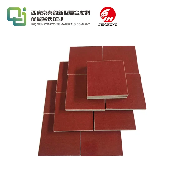
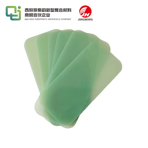
FR4 board insulation is made of continuous fiber glass cloth that has been mixed with epoxy glue under high heat and pressure. The "FR" label means that the material is flame resistant and meets UL94 V-0 standards. This means that the material will put out the fire itself within 10 seconds of being removed from a fuel source. This thermosetting laminate keeps its shape even when temperatures change, which is very important for RF devices that have to deal with heat cycles while they're working. In normal grades, the glass transition temperature (Tg) is usually between 130°C and 140°C. However, high-Tg variants can hit 170°C or higher for uses that require high thermal stress.
A uniform base with a density of 1.85 to 2.10 g/cm³ is made during the manufacturing process. Copper coating choices range from 0.5 oz to 3 oz per square foot. This lets designers choose the best conductor thickness based on how much current they need to carry and how much impedance they want. Standard thicknesses are 0.4mm, 0.8mm, 1.0mm, 1.6mm, and 2.4mm. Custom sizes can be made with CNC cutting, but the rough glass content of the material means that carbide or diamond-coated tools are needed.
Critical Electrical Properties for RF Performance
At 1 MHz, the dielectric constant of FR4 is usually between 4.4 and 4.8, and this number stays pretty stable over a wide range of frequencies. This number has a direct effect on how trace resistance is calculated and how fast signals travel through transmission lines. FR4 has higher dielectric loss than specialized RF laminates. At 1 GHz, its loss tangent (dissipation factor) is about 0.02 and it rises as frequency does. When building circuits that work above 5 to 6 GHz, this trait becomes the main problem because signal loss and phase distortion start to build up.
Breakdown voltage is higher than 40–50 kV when measured parallel to laminate layers. This is enough protection for most RF power amplifier uses below 500 watts. During temperature cycle, the material keeps its shape very well and keeps its mechanical qualities, with a flexural strength exceeding 340 MPa. Water absorption stays below 0.1%, so dielectric strength is maintained even in high-humidity areas. This is a big benefit over paper-phenolic options, which break down when water gets into the substrate.
Advantages and Frequency Limitations
The best thing about FR4 for RF uses is that it is very cost-effective. The prices of materials stay low compared to specialized RF substrates like PTFE-based laminates because they are available all over the world and can be made using well-established infrastructure. The large number of suppliers and short lead times are appreciated by procurement teams. This is especially helpful when project deadlines are tight or when development needs quick feedback cycles.
Even though it is rough, the material can be machined smoothly and can support the complicated shapes needed for impedance matching networks and filter structures. Chemical resistance to common solvents used in manufacturing makes sure that standard PCB fabrication tools can work with the material. Safety rules for consumer gadgets and industrial equipment are met by the flame-retardant qualities, which don't need any extra protective coatings.
But problems start to show up at higher levels. Due to the relatively high loss vector, signal loss goes up a lot above 5 GHz. The dielectric constant changes with temperature by about 150 ppm/°C, which can cause sensitive electronics to have different resonant frequencies. When design engineers look at how suitable FR4 is, they need to think about these features. They should also keep in mind that specialized materials like Rogers laminates work better when budgets allow.

Comparing FR4 with Alternative PCB Materials for RF Use
Performance Characteristics Across Material Types
Choosing the right materials has a big effect on how well an RF circuit works, how hard it is to make, and how much the whole job costs. Knowing how FR4 board technology stacks up against other options helps buying professionals make smart choices that meet technology needs and stay within budget.
When signal loss is very important, Rogers laminates are the best choice for high-frequency uses. At 10 GHz, these PTFE-based materials have loss tangent values as low as 0.002, which is ten times lower than FR4. This makes them perfect for use in millimeter-wave and microwave devices. You can choose from dielectric constants between 2.2 and 10.2, and the tight limits make it possible to control the resistance very precisely. However, the costs of materials are usually 300–500% higher than FR4, and the time it takes to make things is longer because they need to be made in a special way.
Ceramic surfaces have the best thermal conductivity—160 W/mK compared to 0.3 W/mK for FR4—which is important for high-power RF amplifiers that need to get rid of heat quickly. The rigid structure helps with downsizing in military and aircraft uses that need strong materials because of harsh environments. It's hard to make because the material is so flimsy and complicated to work with, and it costs 10 times or more as much as FR4.
Wearable RF devices and other uses that need the ability to bend radiuses benefit from polyimide's flexibility. It has better temperature protection than regular FR4, but its electrical qualities aren't as good as those of specialized RF materials. Metal core printed circuit boards have aluminum or copper base layers for managing heat, which is good for LED drivers and power electronics but not so great for pure RF signal processing.
Selecting the Right FR4 Variant
Specification decisions have a big effect on RF performance within the FR4 family. High-Tg FR4 doesn't change shape when heated up during reflow soldering and long-term use above 130°C, which is very important when RF power amps cause localized heating. The improved physical stability keeps resistance changes to a minimum across a wide range of temperatures.
Copper weight choice strikes a mix between the ability to carry current and the loss of skin effect at RF frequencies. Copper that weighs 2 to 3 ounces is better for power distribution networks, while copper that weighs 0.5 to 1 ounce is better for signal lines where skin depth limits current flow. Surface finish choices (HASL, ENIG, or OSP) affect how well they can be soldered and how reliable they will be over time. ENIG gives fine-pitch components in current RF front-end modules better planarity.
Multi-layer designs allow for the merging of the ground plane and interlayer shielding, which makes the isolation between RF steps better. For stack-up design to work, you need to carefully model the resistance, taking into account how the dielectric constant of FR4 changes over time and how thick it is. Tough thickness control—±10% versus standard ±20%—from suppliers leads to more predictable electrical performance, which justifies small price increases for precise RF uses.
Procurement Considerations for FR4 Boards in RF Projects
Supplier Credibility and Quality Certifications
Decisions about where to get things have long-term effects that go beyond the original prices of materials. Supplier dependability affects project timelines, quality consistency, and the availability of expert assistance over the lifetime of a product. Manufacturers that have been around for a while and have ISO 9001 certification show that they handle quality in an orderly way. This lowers the chances of differences between batches that hurt RF performance.
Following the rules set by NEMA FR-4, MIL-I-24768/27, EN 60893, and ISO 1642 guarantees that materials meet the written requirements. UL approval and ROHS compliance meet the rules in the European and North American markets. Ask for test results that show the dielectric constant, loss tangent, and thermal qualities at the right frequencies, and make sure that the specs meet the needs of the application.
When performance problems happen, manufacturers who can test their products in-house can fix them faster. Technical support teams that know how to deal with problems in RF design are useful for more than just providing materials. They can help with things like optimizing stack-up and figuring out resistance. Over 20 years of engineering teamwork, we've seen how supplier relationships can shorten development times and raise the success rate of first-pass designs.
Minimum Order Quantities and Lead Time Management
Standard FR4 boards usually have lower MOQs than specialized RF laminates—usually between 50 and 100 sheets instead of 500 or more for rare materials. Custom thickness requirements and non-standard measurements may cause MOQs to go up as makers weigh the costs of setup against the number of orders they receive. When procurement managers negotiate annual deals, they get better prices and fixed production capacity, which keeps the supply chain from going up and down.
Lead times depend on how complicated the specifications are and how quickly the seller can make the goods. Standard setups ship in two to four weeks, but it can take up to eight weeks for unique copper weights or special resin formulas. Having extra of the most important RF parts on hand lowers the risks that come up when demand goes up or supply is interrupted. Our combined logistics skills make foreign shipping easier by combining orders for materials with fabrication services to cut down on the time it takes to get everything.
Cost Optimization Strategies
The cost of materials is one part of the overall economy of a job. Look at providers that offer value-added services like precision cutting, edge finishing, or kitting with materials that go well together. These services should lower the need for internal processing. By committing to a certain amount of goods, you can get better prices, and if you buy more than a certain amount each year, you can save 15 to 30 percent.
Landed prices and wait times are affected by where the goods are shipped. Domestic suppliers cut down on shipping times and make contact easier. On the other hand, international suppliers, especially makers with a lot of experience exporting, can often offer lower prices on bigger orders. Balanced buying strategies keep prices low while making sure there is a steady supply of goods by working with a variety of vendors.
Ask for specific quotes that include the grade of the material, the thickness tolerances, the weight of the copper, the surface finish, and the packing. When requirements aren't clear, it leads to extra work or lower performance, which has hidden costs. Clear pricing with detailed breakdowns lets you compare costs correctly and make smart choices that are in line with project budgets and performance goals.
Practical Applications and Performance Optimization of FR4 Boards in RF Devices
Real-World Implementation Examples
Antenna systems that work below 2.4 GHz can easily use FR4 boards. This is especially true in Wi-Fi routers, Bluetooth modules, and ISM band devices, where choosing the right material is based on how much it costs. Patch antenna arrays can have good gain and bandwidth as long as the builders take substrate losses into account and fit the impedance and feed networks in the best way possible. Techniques like ground plane integration and via stitching cut down on unwanted radiation and make pattern control better.
IoT devices use FR4's mechanical security and ease of production in their signal processing units. RF mixers, oscillators, and low-noise amplifiers that work at cellular frequencies (700 MHz to 2.6 GHz) work well as long as dielectric losses are taken into account in the circuit design. The electrical properties of the substrate are used to their fullest through careful layout techniques like controlled impedance traces, suitable ground return lines, and smart component placement.
FR4's strong mechanical qualities and flame protection make it a good choice for power distribution networks in RF equipment. In high-voltage switchgear uses, busbar supports, phase barriers, and insulator frames made from thick FR4 sheets keep the electricity from flowing. Because the material stays the same size under load, it doesn't creep or deform, which could lower safety gaps in power amplifier setups.
Thermal Management Enhancement Techniques
RF power amplifiers produce a lot of heat that needs to be disposed of efficiently. FR4's thermal conductivity (0.3 W/mK) makes it harder for heat to spread than metal-core materials, but design methods can get around this problem. When copper is poured around high-power parts, it forms heat sinks that spread heat over bigger areas of the ground. Thermal vias join parts on the top to ground planes on the bottom, creating paths for heat to flow through the material.
External heat sinks that are connected to thermal contact materials take heat away from the PCB assembly. Strategies for placing components put high-power parts close to the edges of the board, where heat can leave more easily. Temperature tracking during prototype testing confirms thermal models and finds hotspots that need design changes before going into production.
When working temperatures get close to 150°C, high-Tg FR4 types keep their mechanical integrity. This stops warping that hurts electrical performance. If you choose the right glass transition temperature specifications based on the temperature environments you expect, you can be sure of long-term reliability without having to pay more for materials than you need to for uses that work in normal FR4 temperature ranges.
Testing Protocols for RF Reliability
Measurements made by a network tester show the insertion loss, return loss, and impedance accuracy over a wide range of working frequencies. Baseline measures on sample units set standards for performance, and production testing finds any differences in the way the parts were made before they are sent out. By comparing the measured results to the statements made by electromagnetic simulations, design assumptions are checked and problems that need to be looked into are found.
As part of environmental stress testing, parts are put through temperature changes, humidity exposure, and thermal shock patterns that are similar to what would happen in the field. Monitoring electrical factors during accelerated aging methods shows how things break down and proves that the design gaps are sufficient. High-potential testing makes sure that the insulation is solid and that the breakdown voltage requirements include safety margins above standard working voltages.
Conclusion
When frequency bands, performance needs, and cost goals are all in line with what FR4 boards can do, they are very useful in RF applications. By knowing about dielectric qualities, thermal characteristics, and mechanical strengths, you can make smart choices about when FR4 is the best value and when specific substrates are worth the extra money. For procurement to go well, partnerships with suppliers that offer stable quality, quick technical support, and a range of customization options are key. As RF technology moves toward higher frequencies and higher integration densities, material selection continues to balance performance needs against cost considerations. This means that a full analysis of FR4 variants and replacements is necessary for creating competitive products.
FAQ
What maximum operating frequency works reliably with FR4 substrates?
FR4 performs effectively in applications below 5 GHz, where signal attenuation and phase confusion are okay, FR4 works well. Beyond this point, raising the loss tangent makes performance worse, so it's better to use specific low-loss materials, even though they cost more. For certain uses, the realistic frequency limits are set by the circuit topology and the acceptable insertion loss parameters.
How does thermal conductivity affect RF device performance?
Low thermal conductivity (0.3 W/mK) causes localized heating in the steps of a power amplifier, which could change the properties of the components and make the amplifier less efficient. To make up for the limits of the material, strategic copper pours, thermal vias, and heat sinking on the outside are used. For uses with more than 50 watts of power, metal-core options or mixed designs that combine FR4 signal layers with thermally conductive bases often work better.
Can FR4 boards accommodate custom thickness and copper weight specifications?
Manufacturers often make special configurations that meet specific engineering and impedance standards. Copper weights from 0.5 oz to 6 oz per square foot allow for optimal current holding, and thicknesses ranging from 0.2 mm to 6 mm support a wide range of uses. Customization usually adds two to three weeks to the wait time, and based on how complicated the specifications are, it may change the minimum order quantity.
Partner with J&Q for Precision FR4 Board Solutions
J&Q can help you with your RF application problems because they have been making things for over 20 years and have been trading internationally for ten years. Our expert team knows the fine details of dielectric constant limits, thickness accuracy, and surface finish needs that affect how well an RF circuit works. We keep a lot of quality certifications, like ISO standards and UL recognition, to make sure that the materials we use meet strict requirements for tough jobs.
We offer a complete service, from choosing the right materials to shipping them around the world, thanks to our combined logistics skills and long-term partnerships with global trade partners. Our technical support helps you make the best material choices based on your performance goals and budget, whether you're looking for standard FR4 board configurations or creating custom specs for specific RF needs. Email our team at info@jhd-material.com to talk about the needs of your project and get samples to look over. As a supplier of FR4 boards with a lot of experience, we're dedicated to your success by keeping your development schedules on track through quick contact, expert advice, and reliable delivery.
References
Coombs, C. F. (2008). Printed Circuits Handbook, 6th Edition. McGraw-Hill Professional.
Edwards, T. C. & Steer, M. B. (2016). Foundations for Microstrip Circuit Design, 4th Edition. John Wiley & Sons.
Breed, G. (2009). "An Introduction to Defects in Printed Circuit Boards," High Frequency Electronics Magazine, Summit Technical Media.
IPC-4101 Specification for Base Materials for Rigid and Multilayer Printed Boards (2017). IPC - Association Connecting Electronics Industries.
Wadell, B. C. (1991). Transmission Line Design Handbook. Artech House Publishers.
Pozar, D. M. (2011). Microwave Engineering, 4th Edition. John Wiley & Sons.