FR4 Board Warping Under High Heat: Solutions
2026-06-17 17:28:20
Extreme temperatures can cause FR4 board assemblies to bend, which is a major problem that impacts the safety and dependability of the product. This change in shape is caused by differences in the coefficient of thermal expansion (CTE) between the copper layers and the glass-epoxy substrates. These differences are made worse by reflow soldering patterns and stress from the surroundings. To stop bending, you need a complete plan that includes choosing the right materials, making sure the design works best, and improving the process so that the dimensions stay the same during production and use in the field.
Understanding the Problem of FR4 Board Warping Under High Heat
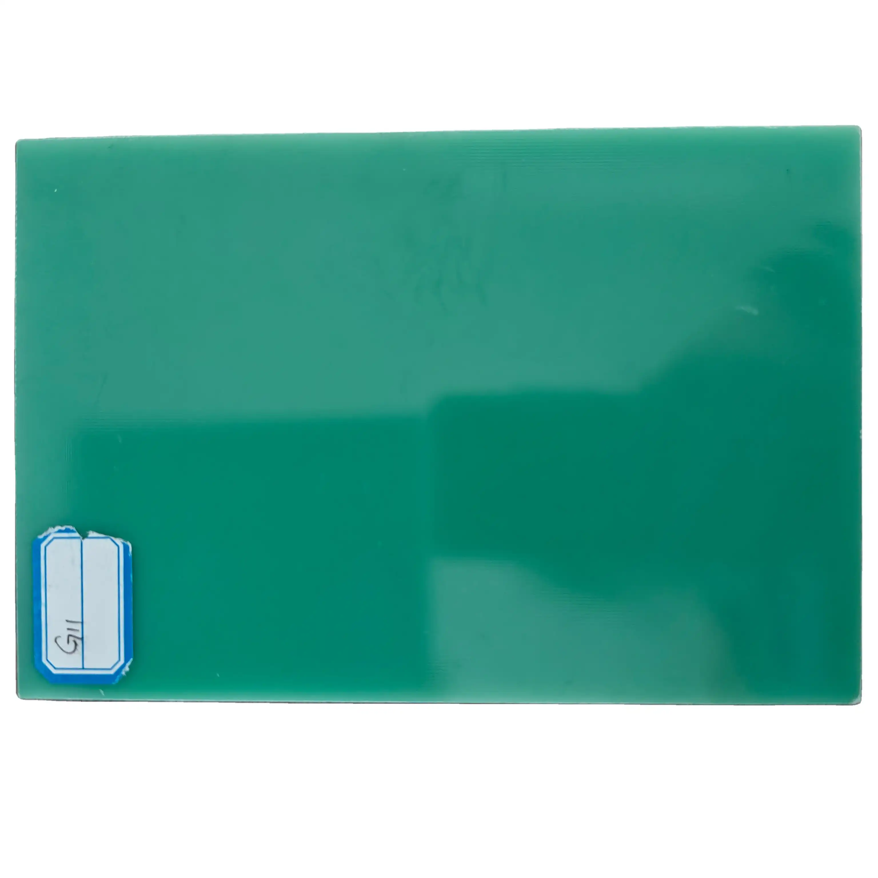
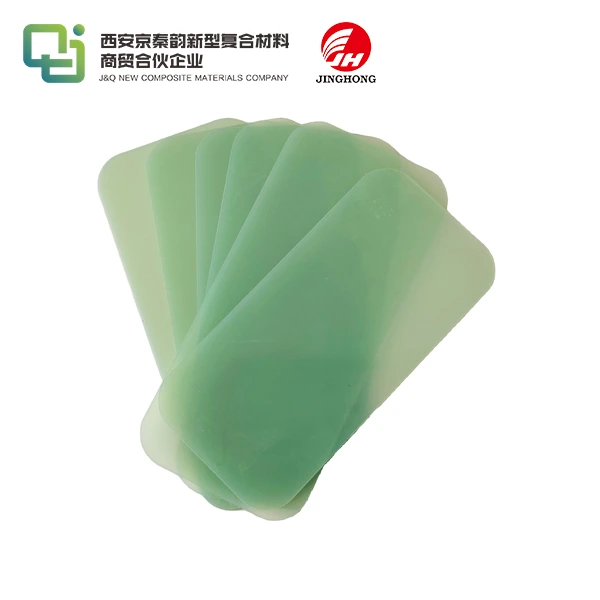
FR4 board insulation is the standard for printed circuit board bases. It is made of continuous filament glass cloth and epoxy resin, which gives it great strength and electrical separation. The material has a density of 1.85–2.10 g/cm³ and a bending strength of more than 340 MPa. This makes it an essential for making switchgear, motor parts, and PCB circuits in the electronics industry.
Why Thermal Warping Occurs
Warping happens when the temperature of epoxy-glass laminates changes during soldering, which usually happens between 240°C and 260°C for lead-free assembly. The difference between copper's CTE (17 ppm/°C) and FR4 board through-plane growth causes stress to build up inside the material. The glass transition temperature (Tg) of standard FR4 board materials is between 130°C and 140°C. Above this temperature, the resin matrix softens, which lets mechanical bending happen. Dimensional instability is caused by uneven copper distribution, not enough lamination pressure, and moisture absorption below 0.2%.
Industrial Implications
Warping has effects that go beyond how it looks. In power distribution equipment, insulation walls that are twisted make arc resistance and phase separation less reliable. To stop thermal runaway routes, automotive battery pack walls need to be very accurate in terms of size. Manufacturers of transformers say that dielectric breakdown voltage drops below the normal >40 kV levels when coil insulation sheets are warped, which puts practical safety at risk. These problems cause warranty claims, output delays, and higher costs for buying things for engineering teams that are in charge of complicated supply lines.

Analyzing Causes of FR4 Board Warping: Material and Environmental Factors
Procurement managers and design engineers can take focused steps to fix problems when they know what the root reasons are. The temperature stability of a product depends on its makeup, how it was made, and the weather outside.
Intrinsic Material Characteristics
The epoxy resin method sets the limits of thermal efficiency. Standard FR4 board uses brominated flame retardants to get UL94 V-0 rating, which means it will put out a fire on its own in 10 seconds. But these additions change the cross-linking density and heat growth behavior of the resin. High-Tg versions (170°C+) use changed epoxy chemicals with naphthalene or multipurpose hardeners to lower CTE and improve shape retention after long-term heat exposure. The mechanical strength of fiberglass is directly related to its weave density, which is measured in grams per square meter. Tighter weaves reduce the number of resin-dominated expansion zones that cause bending.
The quality of the copper-clad material adds another variable. Changes in how well the foil sticks, how rough the surface is treated, and the amount of empty space in the layer cause stress to be distributed unevenly. When buying teams buy materials without checking to see if they meet NEMA FR-4 or IPC-4101 standards, there are differences between batches, which makes it harder to optimize the temperature profile.
Processing and Environmental Stress Factors
Through the use of pressure and curing temperature patterns, multilayer lamination processes add leftover stress. If you don't leave resin at high temperatures long enough, it doesn't fully polymerize. This leaves internal strain that shows up as warping during later heat events. Even though FR4 board can only absorb about 0.1% of water, when stored wetness evaporates during soldering, it creates localized pressure points that make delamination more likely.
When wave soldering or reflowing, uneven heating creates temperature gradients on the board's sides. A difference of 30°C between the top and bottom surfaces causes bending moments that are related to the square of the board thickness. This is why smaller substrates (0.8mm–1.0mm) are more likely to warp than 1.6mm or 2.4mm options that are usually used in power electronics.
Practical Solutions to Minimize FR4 Board Warping
Strategies for reducing damage include choosing the right materials, building designs, and the art of making things. Over the past 20 years of making insulation sheets, we've seen that combined methods offer real benefits over separate ones.
Material Selection and Specification
When you choose high-Tg FR4 board types, you get instant thermal space. Materials that can withstand temperatures up to 170°C Tg stay stiff even after many reflow cycles, which is very important for car uses that need lead-free assembly. Through our work with foreign trade partners, we know that machinery makers are asking for Comparative Tracking Index (CTI) ratings above 600V for high-voltage switchgear parts more and more. This means that premium epoxy formulations with better arc protection are needed.
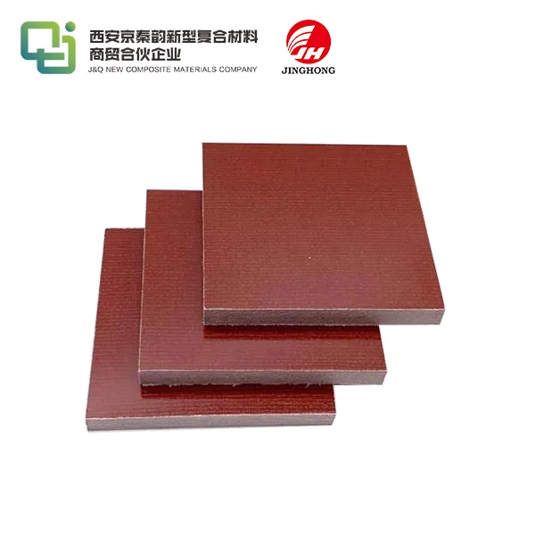
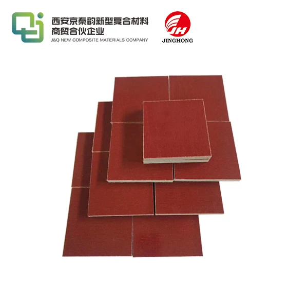
Thickness optimization finds the best balance between heat mass and mechanical strength. Customers in the power sector who use transformer insulation sheets say that 3.0mm thickness is better for maintaining dimensions than 1.6mm options, but CNC machines have a harder time cutting bigger sections. Engineers can exactly meet the needs for thermal resistance with custom thickness options ranging from 0.5 mm to 50 mm.
Certification compliance can't be hacked. ROHS-compliant FR4 boards get rid of lead and halogenated flame retardants, which meets environmental standards and keeps UL recognition. Certifications like MIL-I-24768/27 and EN 60893 (EP GC 202) provide quality assurance systems that procurement experts use when judging suppliers.
Design and Manufacturing Process Controls
Differential growth is kept to a minimum by distributing copper evenly across PCB layers. Stacks that are symmetrical and have similar copper weights on the outside layers lower the bending moments that happen during heat cycles. Thermal via arrays, which usually have a 0.3 mm width and a 1.0 mm grid spacing, make vertical heat transfer lines that even out temperature differences. This, according to thermal simulation studies, lowers hot spots by 15°C to 25°C.
For 50-ohm microstrip lines, controlled impedance designs need exact dielectric thickness tolerances of ±10%. Our logistics integration skills make sure that tolerance requirements are translated into consistent batch quality. This helps appliance makers who need stable mass production of more than 50,000 units per month.
By using thermal profiling to improve the reflow profile, the highest temperature contact time is cut down. Thermal shock can be kept to a minimum by keeping ramp rates below 3°C/second and limiting the time above liquidus to 60–90 seconds. Automatic optical inspection (AOI) systems can find bending greater than 0.5 mm per 100 mm span, which lets process changes be made in real time before the problem spreads.
Strategic Supplier Collaboration
When you work with experienced material providers, you can turn buying things into a smart relationship instead of just a transaction. Our more than ten years of experience in international trade makes it easier to communicate across time zones and technical specs. This cuts down on mistakes that cause deliveries that don't meet requirements. With in-house operations, we can take care of everything, from production to shipping in containers. This cuts wait times for custom epoxy laminate orders from 8–12 weeks to 4–6 weeks.
Quality system certifications, such as ISO 9001 and AS9100, show that a company is dedicated to creating controlled production settings. Third-party testing that confirms the dielectric strength (>30 kV/mm in high humidity), the ability to keep its bending strength after thermal aging, and the ability to stop flames from spreading is what engineering managers need for design validation testing.
Case Studies: Successful Warping Reduction in FR4 PCB Manufacturing
Theoretical methods are supported by examples in the real world. A European company that makes industrial machinery kept having problems with 1.2 mm FR4 boards used in motor control systems bending. When they switched to 2.0mm high-Tg material with even copper distribution, warping went from 1.8mm to 0.3mm across 200mm diagonal measures. This made automatic assembly yields go from 87% to 98% in just three production runs.
During thermal cycle tests (-40°C to 125°C), a tier-1 car supplier that was making battery control systems had delamination. Using special 1.6mm FR4 boards with higher CTI ratings and controlled moisture bake-out processes (125°C for 4 hours before assembly) got rid of all problems in 10,000-cycle validation testing, allowing the product to be qualified ahead of schedule.
When a company that makes power distribution equipment switched to approved FR4 board insulation that meet IEC 60664-1 standards, the amount of scrap they had dropped by 34%. The material's impact strength of 250 J/m and breakdown voltage of over 50 kV parallel to layers stopped arc tracking in high-voltage bus bar support uses. This shows that the specification of the material directly affects its reliability in the field.
Conclusion
To stop FR4 board from twisting when it gets hot, you need to use methods that combine material science, design discipline, and manufacturing precision. Controlled temperature profiles, balanced stack-up designs, and high-Tg epoxy laminates all work together to lower the risk of deformation. Partnering with suppliers that offer flexibility, clear certification, and transportation integration is good for procurement teams. Specificing thickness tolerances, dielectric performance parameters, and flame retardancy standards ahead of time makes sure that products will last for a long time in power systems, car electronics, and industrial machines. Quality keeps getting better over the span of a product by keeping an eye on thermal profiles and the accuracy of each batch of materials.
FAQ
What FR4 thickness best prevents warping in high-temperature applications?
The choice of material is based on the mechanical and heat loads. For most power electronics and car uses, boards with a thickness between 1.6mm and 3.2mm have the best rigidity-to-weight ratios. When structural stability is more important than weight, thinner plates (3.0mm–6.0mm) are best for transformer insulation and high-voltage switchgear. To keep things flat during reflow soldering, thinner choices (0.8mm–1.2mm) need high-Tg formulas and symmetrical copper balance.
How does FR4 compare to aluminum-backed PCBs for heat resistance?
FR4 board has a thermal conductivity of 0.3–0.4 W/m·K, while aluminum core PCBs have a thermal conductivity of 1–3 W/m·K. FR4 board insulation boards, on the other hand, offer better electrical separation (>10^12 Ω surface resistivity) and are more cost-effective for uses that don't need active temperature management. High-Tg FR4 board materials can work continuously at temperatures up to 150°C and still be mechanically sound. This makes them ideal for most industrial and household uses where aluminum's resistance makes grounding difficult.
Can custom FR4 dimensions reduce warping risks?
Of course. Engineers can perfectly match the thermal expansion traits by selecting the right thickness, copper weight distribution, and aspect ratios. Custom panel sizes cut down on wasteful material use and allow for the best placement of markings for automatic assembly. Our production skills allow us to handle orders ranging from small prototypes to large-scale production. This helps with both testing new ideas and switching to full-scale production without having to switch suppliers, which can cause process variability.
Partner with J&Q for Warping-Resistant FR4 Solutions
J&Q sells high-quality epoxy glass laminates that are made to stay stable in harsh industrial settings. We have a variety of high-Tg FR4 boards in stock, as well as unique thickness choices ranging from 0.5mm to 50mm and full ROHS/UL compliance paperwork to meet the needs of buyers around the world. We offer a one-stop service from material selection to foreign shipping, thanks to our more than 20 years of experience in manufacturing and our fully integrated logistics networks. Technical advice is available to engineering teams to help them choose the best materials for motor parts, switchgear insulation, and PCB bases. To make sure it fits your thermal control needs, email info@jhd-material.com and ask for full specs and samples. As a well-known FR4 board seller to the electronics, power, and car industries, we keep batch stability and lead time reliability, which is important for keeping production going. You can look at all of our insulation materials at jhd-material.com.
References
Coombs, Clyde F. Printed Circuits Handbook, 7th Edition. McGraw-Hill Education, 2016.
Harper, Charles A. Electronic Materials and Processes Handbook, 4th Edition. McGraw-Hill Professional, 2018.
IPC-TM-650 Test Methods Manual. Test Methods for Evaluating Printed Board Materials. IPC Association, 2020.
Tummala, Rao R., et al. Fundamentals of Microsystems Packaging. McGraw-Hill Professional, 2001.
Wassink, R.J. Klein. Soldering in Electronics, 2nd Edition. Electrochemical Publications, 1989.
Zhang, G.Q., et al. The Mechanics of Solder Alloy Interconnects. Springer Science+Business Media, 2004.
 拷贝_1755500211555.jpg)
_1753951194967.jpg)