What the Best FR4 Sheet Thickness for Your Application?
2026-03-03 17:27:16
Choosing the right FR4 sheet thickness depends on the needs of your application. For example, 1.6mm is a common thickness for PCB designs, while 0.1mm is very thin and used in mobile devices, and 3.2mm is strong and used in high-power electronics. The best thickness takes into account cost, electrical performance, mechanical strength, and heat control. Some important factors are the dielectric properties for controlling impedance, the structural stability for handling mechanical loads, the need for heat dissipation, and the limitations of manufacturing. Our research team has seen that choosing the right thickness can increase the reliability of a product by up to 40% while also lowering the cost of the materials.
Understanding FR4 Sheet Thickness Standards and Available Options
The market for FR4 sheets follows well-known rules that make sure that supply lines around the world are consistent and reliable. When engineering managers and procurement teams understand these standards, they can make choices that meet their technical needs and stay within their budget.
Common FR4 Thickness Standards in the Industry
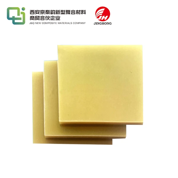
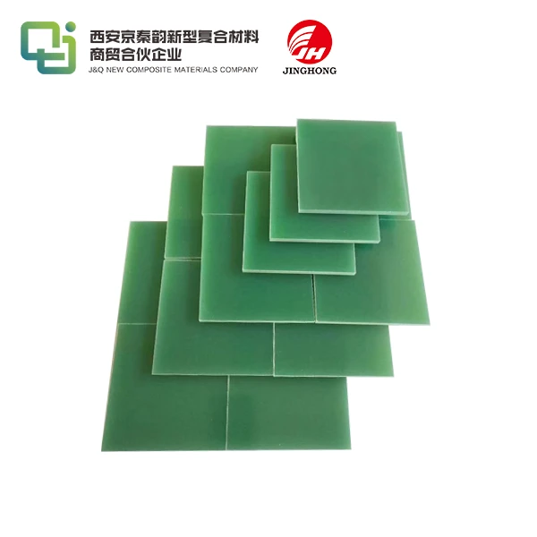
The normal thicknesses for FR4 are set in specific increments that are meant to meet the needs of a wide range of applications. Thicknesses of 0.1mm, 0.2mm, 0.4mm, 0.6mm, 0.8mm, 1.0mm, 1.2mm, 1.6mm, 2.0mm, 2.4mm, and 3.2mm are the most common. Standardized choices like these give manufacturers a way to predict how things will work and make managing inventory easier all along the supply chain.
The 1.6 mm thickness is still the standard in the industry; it's used in about 60% of all PCB uses because it has the best mix of mechanical and electrical properties. In consumer devices, where space is limited, thinner options like 0.8mm and 1.0mm have become more popular. On the other hand, thicker options above 2.0mm are used in industrial and automotive settings that need better durability.
Metric vs Imperial Measurements for Global Procurement
When looking for FR4 products, global procurement teams often come across both metric and imperial units. To convert between metric and imperial measurements, 0.8 mm is equal to 0.031 inches, 1.6 mm is equal to 0.062 inches, and 3.2 mm is equal to 0.125 inches. Because electronics are made all over the world, this two-way method of measurements is necessary. Asian suppliers usually use metric measurements, while North American companies usually use imperial measurements.
Knowing how to use both measurement methods will help you avoid making mistakes that cost a lot of money during the procurement process. To make sure they can communicate clearly with global sellers, many experienced buyers keep conversion charts and list tolerances in both units. This method cuts down on mistakes that could cause delays in production or waste of materials.
Tolerance Levels and Quality Classifications
Tolerances in FR4 thickness have a direct effect on the quality of the finished product and the consistency of production. Tolerances are usually ±0.05mm for materials less than 1.0mm thick and ±0.1mm for materials that are bigger. Premium-grade FR4 has tighter limits of ±0.025mm, which is important for precision tasks like high-frequency circuits or stacking multiple layers of PCBs.
There are different levels of quality, such as commercial grade for applications that need to be cost-effective, industrial grade for applications that need to be more reliable, and military-specification grades for aircraft and defense applications. For each classification, there are specific testing procedures for dielectric strength, flame resistance, and mechanical properties. These make sure that the products work the same way in all kinds of circumstances.

Critical Factors That Determine Optimal FR4 Thickness Selection
To choose the right thickness, you need to carefully look at a number of technical factors that affect both the performance right away and the stability in the long term. Engineering teams have to find a balance between different needs while also taking into account the limitations of production and the costs that come with it.
Electrical Performance Requirements and Impedance Control
Electrical efficiency is the main factor that determines which thickness of FR4 to use, especially when high-frequency signals or exact impedance matching are needed. Because they are thinner, substrates with less parasitic capacitance and better impedance control are perfect for RF uses and high-speed digital circuits. At 1 MHz, the dielectric constant of FR4 stays pretty stable across a range of thicknesses, staying between 4.2 and 4.8.
The estimates for impedance are directly related to the thickness of the substrate, the width of the trace, and the weight of the copper. To keep certain impedance values, thicker FR4 sheets need wider traces, which can affect the density of the circuit and how well the plan works. When designing small electronic devices, design engineers have to think about these trade-offs in order to keep signals safe while also fitting everything in a small place.
Mechanical Strength and Structural Integrity Considerations
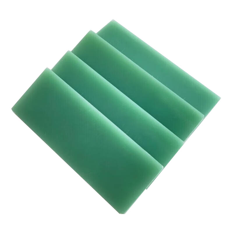
The needs for mechanical performance are very different for different types of equipment, from fragile consumer electronics to tough industrial machinery. FR4 sheets that are thicker have better flexural strength and impact resistance, so they can be used in places where there is vibration, thermal cycles, or physical stress. The flexural strength of normal FR4 is usually between 380 and 450 MPa, and thicker sheets are better at spreading out loads.
In situations where the FR4 sheet has to do two things at once, like insulating electricity and supporting weight, structural factors become very important. Industrial control screens, power distribution equipment, and car parts often need thicker substrates to keep their electrical integrity over a longer service life while also being able to handle mounting stresses and environmental conditions.
Thermal Management and Heat Dissipation Needs
In power devices and high-current applications, thermal performance has a direct effect on how reliable something is. More thermal mass and better heat spreading are provided by thicker FR4 sheets, which helps control hot spots and lowers temperature differences across the circuit board. However, because FR4 doesn't transfer heat very well (about 0.3 W/m·K), thickness by itself can't solve big thermal problems.
The thermal expansion coefficient of FR4 is between 14 and 17 ppm/°C in the XY line and 50 to 70 ppm/°C in the Z-axis. This is something that design engineers need to think about. These characteristics of expansion affect the reliability of the component and the integrity of the solder joint when the temperature changes. This is especially true in industrial and automotive settings where the working temperature ranges are higher than what is recommended for consumer electronics.
Manufacturing Process Limitations and Design Constraints
The best thickness choice is affected by manufacturing capabilities and process limits in a big way. Different types of CNC machining, drilling, and assembly all have different needs for the thickness of the substrate. Thinner materials may develop drilling burrs or delamination during machining, and surfaces that are too thick can make it harder to place components and solder them together.
Assembly factors include the lengths of component leads, the specs of connectors, and the needs for fitting into an enclosure. Standard component lead lengths can work with a PCB thickness of 1.6 mm. Substrates that are thinner or thicker may need special components or assembly changes that make manufacturing more difficult and cost more.
Application-Specific FR4 Thickness Recommendations
Different types of applications need different thickness levels that are best for their specific performance needs and working conditions. By understanding these application-specific needs, you can choose the right materials and make your products more reliable.
Consumer Electronics and Mobile Devices (0.1-0.8mm)
Ultra-thin FR4 substrates are in high demand because consumer electronics uses want to make things smaller and lighter. Smartphones, tablets, and wearable tech usually have thicknesses between 0.1 mm and 0.8 mm to keep the device size as small as possible while still providing good electrical performance. These thin substrates allow for a lot of circuits and work with new packing technologies, such as embedded components and flexible-rigid constructions.
The hard part about working with ultra-thin supports is keeping their mechanical integrity while they are being put together and moved. To keep substrates from warping or getting damaged during production, manufacturers often use special support devices and different ways of handling them. Even with these problems, the desire for smaller gadgets keeps pushing new ultra-thin FR4 materials and methods of production.
Industrial Control Systems and Automation (0.8-1.6mm)
In industrial settings, widths between 0.8mm and 1.6mm are usually chosen to balance performance needs with cost concerns. For these uses to work reliably in harsh environments, the costs of materials must stay low enough to support large-scale production. The moderate thickness range gives enough mechanical strength for industrial mounting systems and works with normal part sizes and assembly methods.
Mixed-signal circuits are often used in control system designs and need to be carefully controlled for impedance and noise separation. The normal thickness of 1.6 mm has been shown to work well in these situations and is still compatible with standard industrial parts and connector systems. This thickness is also strong enough to support larger PCB formats that are popular in industrial control panels.
High-Power Applications and Power Electronics (1.6-3.2mm)
For power electronics, the substrates need to be bigger so they can handle higher current densities and thermal stresses. Thicknesses ranging from 1.6mm to 3.2mm give inverters, motor drives, and power supplies more current-carrying ability and better thermal management. Because the substrate is now thicker, copper traces and via structures can be wider, which is needed for high-current uses.
In power electronics, where substrate thickness helps heat spread and parts cool down, thermal control is very important. More thermal mass and better temperature distribution are provided by thicker FR4 sheets. This helps avoid thermal runaway and extends the life of components. But designers have to weigh the thermal benefits of thicker surfaces against the higher costs of materials and more complicated assembly that comes with them.
RF and Microwave Applications - Special Considerations
When it comes to signal propagation and electromagnetic performance, RF and microwave uses have specific needs when it comes to substrate thickness. Thinner surfaces usually work better at high frequencies because they lose less power and can better control impedance. However, mechanical issues and production limitations often restrict the range of thicknesses that can be used in RF applications.
For some specialized RF uses, you may need custom thickness specs that are best for certain frequency bands and performance goals. Due to its dielectric properties, FR4 is not ideal for very high-frequency applications above 1 GHz. In these cases, specialized low-loss materials may work better, even though they cost more.
Multi-layer PCB Stackup Optimization
When designing a multi-layer PCB, it's important to think about the thickness of each layer and how they will stack up overall. Standard multi-layer structures use core thicknesses between 0.1 mm and 1.6 mm and prepreg materials to get the total thickness and electrical properties that are wanted. The design of the stackup has a direct effect on the success of electromagnetic compatibility, signal integrity, and power distribution.
Stackup optimization is the process of finding the best balance between resistance needs, layer count limits, and the ability to manufacture. Designers with a lot of experience work closely with PCB fabricators to come up with stackup designs that meet electrical needs and can still be made within budget. This way of working together makes sure that the best thickness is chosen for all layers in complicated designs with many layers.
Evaluating Cost vs Performance Trade-offs in Thickness Selection
To get the best price, you have to carefully look at how much the materials cost, how hard the making process is, and how reliable the product will be in the long run. By understanding these trade-offs, you can make smart decisions that balance the need for efficiency with the limitations of your budget.
Material Cost Analysis Across Different Thickness Options
The price of FR4 material goes up or down almost linearly with thickness. However, premium grades and special formulas cost more per unit volume. The standard commercial-grade FR4 is a great value for most uses, while the higher-performance grades are worth the extra cost because they are more reliable and work better. Standard thickness choices are often better for volume pricing because they are easier to find in the market and there are more suppliers competing for business.
Instead of just looking at material prices, procurement teams should look at the total cost of ownership. Thinner surfaces might need special handling or processing, which raises the cost of production. On the other hand, thicker materials might make designs simpler, which lowers the number of parts and the difficulty of putting them together. In the end, these extra cost factors often make up for differences in material prices.
Manufacturing Complexity and Processing Costs
The difficulty of manufacturing changes a lot depending on the thickness of the substrate, which affects both the cost of production and the quality of the final product. Ultra-thin surfaces need special handling tools and different processes, which raise the cost of manufacturing. On the other hand, materials that are too thick can make drilling, routing, and putting them together harder. It is easiest to make things in most factories because the normal thickness of 1.6 mm doesn't require any special tools.
Processing costs take into account processes like drilling, routing, finishing the surface, and putting the parts together. For longer drilling processes and maybe even special tools, thicker substrates are needed, while thin materials need to be handled carefully to avoid damage during production. Manufacturers with a lot of experience figure out the best ways to make things in the thickness ranges they want. This way, they can get higher results and lower costs.
Long-term Reliability and Maintenance Considerations
Long-term dependability often justifies higher original material costs because it means less maintenance and a longer life for the product. It is common for thicker substrates to last longer and be more resistant to environmental pressures. This makes them good for uses where field service costs are high. Thicker materials are more mechanically stable, which means that solder joints and parts breaking during use are less likely to happen.
When doing a reliability study, you should look at the whole working environment, such as changes in temperature and humidity, the amount of vibration, and the chance of chemical contamination. Applications that need a lot of dependability may benefit from choosing a thickness that is on the conservative side. This gives them a buffer against possible failure modes, even if it means paying more for the material up front.
Supply Chain Availability and Lead Time Factors
When choosing a practical thickness, supply chain factors play a big role, especially when producing a lot of things or meeting short delivery dates. Standard thickness choices usually have better availability and shorter lead times because they have more suppliers who can help and more inventory on hand. For specialized thicknesses, lead times may need to be longer or minimum order quantities may need to be higher, which can affect how production is planned and how much operating capital is needed.
Problems in the global supply chain have shown how important it is to have a variety of suppliers and good inventory management. Having multiple approved suppliers and knowing what thicknesses they can offer helps keep production going even when there are problems in the supply chain. Planning your inventory strategically for important thickness requirements can help you avoid production delays and get the most out of your working capital investment.
Conclusion
To choose the best FR4 sheet thickness, you need to carefully look at the electrical, mechanical, heat, and cost factors that are unique to each application. The standard width of 1.6 mm works well for most general-purpose uses, but thinner or thicker options may be needed for specific situations. Systematic analysis of performance standards, manufacturing constraints, and supply chain factors is key to success. This article describes a decision framework that helps engineering teams balance different needs and make the best thickness choice that meets both technical performance and business goals while also being reliable and cost-effective in the long run.
FAQ
What is the most commonly used FR4 sheet thickness for standard PCB applications?
The most widely used thickness for standard PCB applications is 1.6mm (0.062 inches). This thickness provides an optimal balance between mechanical strength, electrical performance, and cost-effectiveness for most general-purpose electronics applications. The 1.6mm standard has become the industry benchmark due to its compatibility with standard components, assembly processes, and manufacturing equipment.
How does FR4 sheet thickness affect signal integrity in high-frequency applications?
Thinner substrates generally provide better signal integrity for high-frequency applications due to reduced parasitic capacitance and shorter signal paths. However, thickness must be carefully balanced with mechanical requirements and impedance control needs. The relationship between thickness and electrical performance becomes more critical above 100 MHz, where substrate effects significantly influence signal quality and electromagnetic compatibility.
Can I use different FR4 thicknesses within the same product design?
Yes, using different thicknesses within the same product is common, especially in complex multi-board systems. However, ensure compatibility in terms of connector heights, mechanical interfaces, and thermal expansion characteristics. Mixed-thickness designs require careful consideration of assembly processes and may necessitate specialized components or mounting hardware to accommodate the thickness variations.
Partner with J&Q for Expert FR4 Sheet Solutions
J&Q brings over 20 years of manufacturing expertise and 10 years of international trading experience to help you select the perfect FR4 sheet thickness for your application. Our technical specialists provide comprehensive consultation services that evaluate your specific requirements and recommend optimal material solutions. With our in-house logistics capabilities, we deliver one-stop service from specification through delivery. Contact our engineering team at info@jhd-material.com for customized thickness recommendations, competitive pricing, and fast global delivery.
References
National Electrical Manufacturers Association. "Industrial Laminating Thermosetting Products." NEMA Standards Publication LI 1-1998, 2018.
Coombs, Clyde F. "Printed Circuits Handbook." McGraw-Hill Professional, 7th Edition, 2016.
Institute for Printed Circuits. "PCB Substrate Selection Guidelines for High-Frequency Applications." IPC Technical Report, 2019.
International Electrotechnical Commission. "Specifications for Individual Types of Winding Wires - Part 0-4: General Requirements - Glass-Fibre Braided Resin or Varnish Impregnated, Bare or Enamelled Round Copper Wire." IEC 60317-0-4, 2020.
Blackwell, Glenn R. "Electronic Packaging and Interconnection Handbook." CRC Press, 4th Edition, 2018.
Association Connecting Electronics Industries. "Requirements for Printed Boards." IPC-6012D Standard, 2021.